Enabling hardware navigation buttons on Linux

 The Xiaomi Mi Note 2 is old enough to (fortunately) have hardware navigation buttons. Let us see what it takes to make them work on the mainline Linux kernel.
This is the first driver I ever wrote. The simplicity of I2C input devices, especially one with just 2 buttons made it a perfect entry point into driver development.
Collecting information
Usually the first step in enabling hardware on the mainline kernel is to take a look at the stock device tree. For the un-initiated, a Device Tree is a method of describing hardware. The OS reads a device tree to find out what hardware is available on the device it is running on and how it is wired up so that it can properly operate it.
The chip that controls hardware navigation buttons is usually called a touchkey controller. Many devices combine that functionality into the touchscreen, placing the navigation buttons in a specific zone, then treating touches in that zone as key presses.
However, that does not seem to be the case in this device.
Looking at the stock device tree, this node is found:
cyttsp_streetfighter_p2@28 {
	compatible = "cypress,sf3155";
	reg = <0x28>;
	interrupt-parent = <&tlmm>;
	interrupts = <77 0x2002>;
	cyttsp,soft-reset;
	cyttsp,irq-gpio = <&tlmm 78 0x2002>;
	cyttsp,irqflags = <0x2002>;
	cyttsp,input-name = "cyttsp_button";
	cyttsp,key-num = <2>;
	cyttsp,key-codes = <139 158>;
	cyttsp,button-status-reg = <0x4A>;
	cyttsp,bootloader-addr = <0x56>;
	cyttsp,config-array-size = <1>;
	cyttsp,standby-reg = <0x01>;
	cyttsp,softreset-reg = <0x05>;
	pinctrl-names = "pmx_btn_active", "pmx_btn_suspend";
	pinctrl-0 = <&btn_active_a4>;
	pinctrl-1 = <&btn_suspend_a4>;
	cyttsp,cfg_1 {
		cyttsp,hw-version = <0x84>;
		cyttsp,fw-name = "cyttsp_button_no_shielding.fw";
	};
};
It is likely to be the touchkey controller; since it is on the same I2C bus as the touchscreen. This line, however, makes it certain:
cyttsp,key-codes = <139 158>;
Looking at linux-event-codes.h, these key codes translate to KEY_MENU and KEY_BACK, which are the functions of the navigation buttons.
Using the compatible string, the driver that matches this node in the downstream kernel can be found:
drivers/input/touchscreen/cyttsp_button.c:1561:
static struct of_device_id cyttsp_match_table[] = {
	{ .compatible = "cypress,sf3155",},
	{ },
};
Cypress Streetfighter
 Cool name, right? You don’t see components named like this everyday…
Writing a driver
We start off with the general driver structure, which is similar across all kinds of drivers:
struct device_data {
	...
};

static int device_probe(struct class_device *cdev)
{
	...
}

static int device_remove(struct class_device *cdev)
{
	...
}

static struct of_device_id id_table[] = {
	{ .compatible = "vendor,device" },
	{ /* sentinel */ }
};
MODULE_DEVICE_TABLE(of, id_table);

static struct class_driver device_driver = {
	.driver {
		.name = "driver_name",
		.of_match_table = id_table
	}
	.probe = device_probe,
	.remove = device_remove
};
module_class_driver(device_driver);
Now to put it in more detail:
struct device_data
This is an optional struct. It is conventionally used to hold all information about the device, usually collected during probing, and pass it to functions in the driver.
static int device_probe(struct class_device *cdev)
This is the probe function. It is the first function called in any driver, and is used to allocate resources for the driver, collect information about the hardware and initialize it.
static int device_remove(struct class_device *cdev)
An optional function used to deinitialize the hardware if needed, as well as free any resources that have to be explicitly freed.
static struct of_device_id id_table[] = {
	{ .compatible = "vendor,device" },
	{ /* sentinel */ }
};
MODULE_DEVICE_TABLE(of, id_table);
This table contains compatible strings used to match nodes in the device tree with the driver. When Linux finds a node with a matching compatible string, it loads an instance of the driver and passes the device tree node to it.
static struct class_driver device_driver = {
	.driver {
		.name = "driver_name",
		.of_match_table = id_table
	}
	.probe = device_probe,
	.remove = device_remove
};
module_class_driver(device_driver);
This last struct holds information about the driver, as well as pointers to the probe and remove functions. it is used to register the driver.
There are several driver classes, which are part of the multiple subsystems of the kernel. Each one has a slightly different driver structure. The main differences are marked with the class placeholder above.
The Linux Kernel Documentation is quite useful when it comes to writing a driver. It always helps to read about the subsystems and frameworks needed for a specific device when writing a driver for it. For this device, the Input and I2C subsystems are the ones of interest to us:
This driver will follow the structure shown in the Implementing I2C device drivers page, and use bits from the Creating an input device driver page as needed.
First steps
The first step is to define a data struct to hold information that has to be moved around. Initially, this will hold pointers to the i2c_client and input_dev of this device. It will be later expanded as needed.
struct cypress_sf_data {
	struct i2c_client *client;
	struct input_dev *input_dev;
};
Now, a probe function is added:
static int cypress_sf_probe(struct i2c_client *client,
				const struct i2c_device_id *id)
{
	return 0;
}
This will contain everything required to acquire resources for the driver as well as to initialize the hardware.
First, memory is allocated for a struct cypress_sf_data. This struct will be used throughout the life of the driver.
	struct cypress_sf_data *touchkey;

	touchkey = devm_kzalloc(&client->dev, sizeof(*touchkey), GFP_KERNEL);
	if (!touchkey)
		return -ENOMEM;
devm_kzalloc is more or less the kernel equivalent of calloc. It allocates memory and initializes it to zero. This function can fail and return NULL, in which case the -ENOMEM error code must be returned to signal inability to allocate memory
Now the struct can be filled with data. A pointer to the I2C client is kept for later use:
	touchkey->client = client;
	i2c_set_clientdata(client, touchkey);
i2c_set_clientdata stores a pointer in client to touchkey, which can later be retrieved using i2c_get_clientdata. This is useful in functions where touchkey cannot be passed as an argument, but i2c_client is passed.
With all of this out of the way, we can start to focus on initializing the hardware.
Unfortunately, datasheets are nowhere to be found, so the only sources of information about this touchkey controller are the downstream device tree and driver written by Xiaomi.
Analyzing the downstream driver
The probe function of the downstream cyttsp-button driver should contain everything we need to know about initializing the touchkey controller.
It starts off by initializing a data struct, similar to our driver:
	if (client->dev.of_node) {
		pdata = devm_kzalloc(&client->dev,
				sizeof(struct cyttsp_button_platform_data), GFP_KERNEL);
		if (!pdata) {
			dev_err(&client->dev, "Failed to allocate memroy for pdata\n");
			return -ENOMEM;
		}
Then, it parses information from the device tree:
		error = cyttsp_button_parse_dt(&client->dev, pdata);
		if (error)
			return error;
Parsing the device tree node
Looking at cyttsp_button_parse_dt, the main device tree properties are found.
It starts off by reading the Interrupt Request (IRQ) GPIO pin:
	pdata->irq_gpio = of_get_named_gpio_flags(np, "cyttsp,irq-gpio",
				0, &pdata->irq_gpio_flags);
This is the matching property in the device tree:
cyttsp,irq-gpio = <&tlmm 78 0x2002>;
When a change occurs in the state of the buttons, this pin becomes active and triggers an interrupt to handle the change.
It then goes on to read other properties such as cyttsp,input-name, cyttsp,cut-off-power and cyttsp,soft-reset. These properties are not essential so they can be skipped for now.
After that, it reads addresses of a few registers:
	ret = of_property_read_u32(np, "cyttsp,button-status-reg",
			&temp_val);
	...

	ret = of_property_read_u32(np, "cyttsp,standby-reg",
			&temp_val);
	...
	if (pdata->soft_reset) {
		ret = of_property_read_u32(np, "cyttsp,softreset-reg",
				&temp_val);
		...
Getting button status is done by reading the status register, so this register is important.
Next, it reads a bootloader address:
	ret = of_property_read_u32(np, "cyttsp,bootloader-addr",
			&temp_val);
	if (ret)
		dev_err(dev, "Unable to read bootloader address\n");
	else
		pdata->bootloader_addr = (u8)temp_val;
This touchkey controller has some on-chip flash memory to store firmware, and this address is used in a firmware flashing routine. The chip comes with firmware preinstalled and there is no need to update it, so this is not necessary.
Finally, It reads information about the available keys:
	ret = of_property_read_u32(np, "cyttsp,key-num", &temp_val);
	if (ret) {
		dev_err(dev, "Unable to read key num\n");
		return ret;
	} else
		pdata->nbuttons = temp_val;

	if (pdata->nbuttons != 0) {
		pdata->key_code = devm_kzalloc(dev,
					sizeof(int) * pdata->nbuttons, GFP_KERNEL);
		if (!pdata->key_code)
			return -ENOMEM;
		ret = of_property_read_u32_array(np, "cyttsp,key-codes",
						pdata->key_code, pdata->nbuttons);
		if (ret) {
			dev_err(dev, "Unable to read key codes\n");
			return ret;
		}
	}
Here it gets the number of keys available and their codes. This is important, so it will be implemented in our driver.
It also reads a cyttsp,config-array-size property, which has the number of available configurations. It seems that muliple configurations can be used with a set of firmware files, by loading the corresponding file for the needed configuration. This device only has one configuration, so we do not have to worry about this.
Regulators
Once it is done parsing the device tree node, cyttsp_button_probe calls cyttsp_initialize_regulator. These lines summarize the function:
data->regulator_vdd = devm_regulator_get(&client->dev, "vdd");
data->regulator_avdd = devm_regulator_get(&client->dev, "avdd");
ret = regulator_enable(data->regulator_vdd);
ret = regulator_enable(data->regulator_avdd);
It gets two regulators: a digital supply vdd and an analog supply avdd. These regulators supply the digital and analog parts of the IC. It then enables them to power on the chip.
After that, it invokes a firmware update routine. As said before, this is not necessary for now.
Interrupts
With regulators initialized, it goes on to request a GPIO pin for an interrupt:
error = gpio_request(pdata->irq_gpio, "cyttsp_button_irq_gpio");
Then sets its direction:
error = gpio_direction_input(pdata->irq_gpio);
A while later, it allocates an IRQ using the GPIO pin it got:
	error = request_threaded_irq(client->irq, NULL, cyttsp_button_interrupt,
					pdata->irqflags, client->dev.driver->name, data);
Now, an interrupt will be triggered whenever a signal is received on the GPIO pin. This allows for handling changes in button states as they happen. A more in-depth look at cyttsp_button_interrupt, which is the handler for this interrupt, will come later.
This amount of information should be enough to complete the probe function of our new driver.
Probing the device
Regulators
Before anything else, the regulators are acquired. A new struct is added to cypress_sf_data:
struct cypress_sf_data {
	...
	struct regulator_bulk_data regulators[2];
};
This struct will hold names of the required supplies. Back to cypress_sf_probe:
	touchkey->regulators[0].supply = "vdd";
	touchkey->regulators[1].supply = "avdd";
Now they can be acquired using devm_regulator_bulk_get:
	devm_regulator_bulk_get(&client->dev,
				ARRAY_SIZE(touchkey->regulators),
				touchkey->regulators);
devm_regulator_bulk_get is a device resource managed (devm) wrapper of regulator_bulk_get that automatically frees resources when they are not needed, such as when this driver instance is destroyed, or when it fails to acquire all resources and returns an error code. That makes it unnecessary to manually free them in a remove function. It takes a pointer to the struct device of this device, number of regulators, and a pointer to the struct regulator_bulk_data filled with names earlier. It may fail and return an error code, so that has to be handled correctly:
	int error;
	...

	error = devm_regulator_bulk_get(&client->dev,
					ARRAY_SIZE(touchkey->regulators),
					touchkey->regulators);
	if (error) {
		dev_err(&client->dev, "Failed to get regulators: %d\n", error);
		return error;
	}
If an error occurs, this will print an error message in the kernel log, then return the error code.
Key codes
Next, the key codes are read from the device tree. struct cypress_sf_data is further expanded with two new elements:
struct cypress_sf_data {
	...
	u32 *keycodes;
	int num_keys;
}
Then those elements are set:
	touchkey->num_keys = device_property_read_u32_array(&client->dev,
						"linux,keycodes", NULL, 0);
device_property_read_u32_array returns the number of elements in an array property when NULL is passed
A vendor-specific property name like cyttsp,key-codes should not be used here; since a common linux,keycodes property exists. Common property names are preferred over vendor-specific names (see “DOs and DON’Ts for designing and writing Devicetree bindings”).
Also, a cyttsp,key-num property is not necessary; passing NULL instead of an array makes device_property_read_u32_array return the number of elements in the device tree array.
It can also return an error code, such as when it fails to find the property in the device tree node. Instead of just stopping at it though, it is possible to add a default to fall back to:
	if (touchkey->num_keys < 0) {
		/* Default key count */
		touchkey->num_keys = 2;
	}
With the key code count known, memory is allocated for an array to hold the key codes:
	touchkey->keycodes = devm_kzalloc(&client->dev,
				sizeof(u32) * touchkey->num_keys, GFP_KERNEL);
	if (!touchkey->keycodes)
		return -ENOMEM;
The codes are then read from the device tree through a second call to device_property_read_u32_array, passing touchkey->keycodes instead of NULL this time:
	error = device_property_read_u32_array(&client->dev, "linux,keycodes",
						touchkey->keycodes,
						touchkey->num_keys);
Again, this can fail, in which case a warning message is printed in the kernel log and default key codes are used.
	if (error) {
		dev_warn(&client->dev,
			"Failed to read keycodes: %d, using defaults\n", error);

		/* Default keycodes */
		touchkey->keycodes[0] = KEY_BACK;
		touchkey->keycodes[1] = KEY_MENU;
	}
Powering up the IC
Now would be a good time to power up the chip. That is done by calling regulator_bulk_enable which enables all regulators in the struct regulator_bulk_data passed to it (vdd and avdd in this case).
	error = regulator_bulk_enable(ARRAY_SIZE(touchkey->regulators),
					touchkey->regulators);
	if (error) {
		dev_err(&client->dev, "Failed to enable regulators: %d\n", error);
		return error;
	}
The input subsystem
With most of the initializion done, it is time to register an input device. The Creating an input device driver describes the process in detail, as well as other input-related functions which will be used later. For now, the process will be as follows:
- Allocate an input device structure (
struct input_dev); - Add some general information about the device to the structure;
- Set device capabilites;
- Register the input device.
A struct *input_dev was added to struct cypress_sf_data at the beginning. A call to devm_input_allocate_device would allocate an input device and return a pointer to it, which will be stored in the struct *input_dev added to struct cypress_sf_data earlier:
	touchkey->input_dev = devm_input_allocate_device(&client->dev);
	if (!touchkey->input_dev) {
		dev_err(&client->dev, "Failed to allocate input device\n");
		return -ENOMEM;
	}
Then, the name and bus type of the device are set. The device name will be used in other places, so it is better to define it:
#define CYPRESS_SF_DEV_NAME "cypress-sf"
	touchkey->input_dev->name = CYPRESS_SF_DEV_NAME;
	touchkey->input_dev->id.bustype = BUS_I2C;
The third step is to set the capabilities of the input device. This is a touchkey controller, so it has a set of keys, each with its own key code:
	for (key = 0; key < touchkey->num_keys; ++key)
		input_set_capability(touchkey->input_dev, EV_KEY,
					touchkey->keycodes[key]);
This iterates through the key codes acquired from the device tree earlier, and adds a key capability with a key code to the input device.
Finally, the input device is registered:
	error = input_register_device(touchkey->input_dev);
	if (error) {
		dev_err(&client->dev,
			"Failed to register input device: %d\n", error);
		return error;
	}
At this point, the driver is ready to signal input events to the input subsystem, but it still has no way of detecting button state changes. This is where the status interrupt comes into play.
An interrupt line is now allocated for the status interrupt:
	error = devm_request_threaded_irq(&client->dev, client->irq,
					NULL, cypress_sf_irq_handler,
					IRQF_ONESHOT,
					CYPRESS_SF_DEV_NAME, touchkey);
	if (error) {
		dev_err(&client->dev,
			"Failed to register threaded irq: %d", error);
		return error;
	}
devm_request_threaded_irq summarizes what the downstream driver does to get the interrupt line in one function. It reads the interrupt line from the device tree interrupts property, and does everything needed to allocate an IRQ. cypress_sf_irq_handler is the handler function for this interrupt, which will be called every time an IRQ is received.
This sums up the probe function. Now the driver is ready to receive button state changes then signal input events correspondingly, the thing it does in the status interrupt handler.
Handling the status interrupt
The touchkey controller sends an IRQ when any of the keys is pressed or released. This allows the driver to check the button states only when they change. The downstream driver has this interrupt handler:
static irqreturn_t cyttsp_button_interrupt(int irq, void *dev_id)
{
	struct cyttsp_button_data *data = dev_id;
	struct cyttsp_button_platform_data *pdata = data->pdata;
	bool curr_state, new_state;
	bool sync = false;
	u8 val;
	u8 key;
	unsigned long keystates;

	if (data->enable) {
		val = cyttsp_read_reg(data, CYTTSP_REG_TOUCHMODE);
		if (val < 0) {
			dev_err(&data->client->dev, "Failed to read touch mode reg\n");
			return IRQ_NONE;
		} else {
			mutex_lock(&data->input_dev->mutex);
			data->glove_mode = !!(val & (1 << CYTTSP_GLOVE_MODE_SHIFT));
			mutex_unlock(&data->input_dev->mutex);
		}

		val = cyttsp_read_reg(data, pdata->button_status_reg);
		if (val < 0) {
			dev_err(&data->client->dev, "Failed to read status!\n");
			return IRQ_NONE;
		}

		keystates = (unsigned long)val;

		for (key = 0; key < pdata->nbuttons; key++) {
			curr_state = test_bit(key, &data->keystatus);
			new_state = test_bit(key, &keystates);

			if (curr_state ^ new_state) {
				cyttsp_report_key(data, pdata->key_code[key],
						!!(keystates & (1 << key)));
				sync = true;
			}
		}

		data->keystatus = keystates;

		if (sync)
			input_sync(data->input_dev);
	}

	return IRQ_HANDLED;
}
Before doing anything, it checks an enable element in its data struct. Our driver does not have one, so that can be skipped.
Then it checks if the touch mode changed:
		val = cyttsp_read_reg(data, CYTTSP_REG_TOUCHMODE);
		if (val < 0) {
			dev_err(&data->client->dev, "Failed to read touch mode reg\n");
			return IRQ_NONE;
		} else {
			mutex_lock(&data->input_dev->mutex);
			data->glove_mode = !!(val & (1 << CYTTSP_GLOVE_MODE_SHIFT));
			mutex_unlock(&data->input_dev->mutex);
		}
This touchkey controller has a normal mode and a glove mode, possibly for better touch detection with gloved fingertips. Modes are not implemented in our driver as they are not essential, so this part can be skipped too.
Now the important part begins. It first reads the status register, which is 0x4a according to the downstream device tree:
val = cyttsp_read_reg(data, pdata->button_status_reg);
Then it casts the value it reads to an unsigned long variable named keystates.
The status register stores button states in a bit field, where each bit corresponds to a button. 1 is a pressed button, and 0 is the opposite.
Now it iterates through registered keys (read earlier from the device tree), and gets the old and new states of each. After that, it is just a simple XOR operation to determine which ones changed.
		for (key = 0; key < pdata->nbuttons; key++) {
			curr_state = test_bit(key, &data->keystatus);
			new_state = test_bit(key, &keystates);

			if (curr_state ^ new_state) {
				cyttsp_report_key(data, pdata->key_code[key],
						!!(keystates & (1 << key)));
				sync = true;
			}
		}
Then for each key that had a state change, it calls cyttsp_report_key, and sets sync = true for a reason seen later.
static void cyttsp_report_key(struct cyttsp_button_data *data,
		int key, int status)
{
	if (key == KEY_MENU)
		input_report_key(data->input_dev,
				data->enable_reversed_keys ? KEY_MENU : KEY_BACK, status);
	else if (key == KEY_BACK)
		input_report_key(data->input_dev,
				data->enable_reversed_keys ? KEY_BACK : KEY_MENU, status);
	else
		input_report_key(data->input_dev, key, status);
}
This function is just a wrapper for input_report_key, with the sole purpose of allowing the back and menu buttons to be swapped. There should be better ways to implement this – possibly in userspace – so it will not be implemented it in our driver.
Finally, it stores the new states to use as old states in the next status interrupt,
data->keystatus = keystates;
then calls input_sync, which makes the input subsystem send input events according to the previous calls to input_report_key. It uses the sync variable from earlier to check if the status had changed:
		if (sync)
			input_sync(data->input_dev);
Writing an interrupt handler
Using the previous findings, a new interrupt handler is written.
static irqreturn_t cypress_sf_irq_handler(int irq, void *devid)
{
	...

	return IRQ_HANDLED;
}
Interrupt handlers have an irqreturn_t return type, which is an enum with a few entries:
/**
 * enum irqreturn
 * @IRQ_NONE		interrupt was not from this device or was not handled
 * @IRQ_HANDLED		interrupt was handled by this device
 * @IRQ_WAKE_THREAD	handler requests to wake the handler thread
 */
enum irqreturn {
	IRQ_NONE		= (0 << 0),
	IRQ_HANDLED		= (1 << 0),
	IRQ_WAKE_THREAD		= (1 << 1),
};

typedef enum irqreturn irqreturn_t;
and as arguments, they take int irq, the interrupt line that signaled the IRQ, and a void *dev_id, which can be used to pass data to the interrupt handler. These arguments correspond to what was passed when allocating the interrupt, which were client->irq and the data struct touchkey.
As such, void *devid can be casted to a struct cypress_sf_data *:
struct cypress_sf_data *touchkey = devid;
Reading the status register
The I2C subsystem provides a function to read a byte from a register: i2c_smbus_read_byte_data. It takes the I2C client and the register address as arguments, and returns the read value, or a negative error code when it fails.
The register address will be defined in the driver instead of the device tree this time:
#define CYPRESS_SF_REG_BUTTON_STATUS 0x4a
Then i2c_smbus_read_byte_data can be used to read the status register, and store the value in an int val variable:
	int val;

	val = i2c_smbus_read_byte_data(touchkey->client,
					CYPRESS_SF_REG_BUTTON_STATUS);
As usual, errors must be handled properly. Since this is an interrupt handler, IRQ_NONE must be returned after an error to signal the inability to handle the interrupt:
	if (val < 0) {
		dev_err(&touchkey->client->dev, "Failed to read button status: %d",
			val);
		return IRQ_NONE;
	}
val can then be casted to an unsigned long keystates for later operations:
	unsigned long keystates;
	...

	keystates = val;
(I am not quite sure if this is necessary, but it is what I did in the original driver, so I will proceed with it)
Finding status changes
Similar to the downstream driver, an XOR operation is used to find which button states changed. For this, keeping track of the status history is needed, so a keystates element is added to struct cypress_sf_data to hold the current key states (which become the old key states when the status interrupt handler is called):
struct cypress_sf_data {
	...
	unsigned long keystates;
}
Then, an unsigned long changed is defined to hold the XOR result:
unsigned long keystates, changed;
Instead of using the XOR operator (^), bitmap_xor can be used:
	bitmap_xor(&changed, &keystates, &touchkey->keystates,
		   touchkey->num_keys);
This will perform an XOR operation between keystates and touchkey->keystates, or in other words, the new and old states. The result will then be stored in changed.
Next, using for_each_set_bit to iterate through each bit (or key state), the new state is reported using input_report_key:
	for_each_set_bit(key, &changed, touchkey->num_keys) {
		new_state = keystates & BIT(key);
		dev_dbg(&touchkey->client->dev,
				"Key %d changed to %d", key, new_state);
		input_report_key(touchkey->input_dev,
				touchkey->keycodes[key],
				new_state);
	}
For debugging purposes, a debug message is added as well.
Finally, input_sync is called to synchronize the states with the input subsystem and let it send input events:
input_sync(touchkey->input_dev);
Then the new key states are stored in the keystates element of the data struct to be used in the next status interrupt:
touchkey->keystates = keystates;
With that, the driver becomes mostly complete.
Final touches
Adding a kconfig entry and a line to the Makefile is needed to build it. That and other additions such as power managment callbacks and a device tree schema are included in the final patchset.
Enabling the touchkey controller
With a driver written, all it would take to make the navigation buttons work is to add a device tree node.
The touchkey controller is connected to the 6th I2C bus of BLSP 2 on the MSM8996 SoC, so a node is added there:
&blsp2_i2c6 {
	touchkeys: cypress-sf@28 {
		compatible = "cypress,sf3155";
		reg = <0x28>;
	};
};
compatible is the same string added to the match table in the driver, while reg, which specifies the I2C address, is taken from the downstream device tree.
Next, the status interrupt is added:
		interrupt-parent = <&tlmm>;
		interrupts = <77 IRQ_TYPE_EDGE_FALLING>;
interrupt-parent specifies the interrupt controller that provides this interrupt, which in this case is TLMM, the GPIO controller.
interrupts specify the interrupt lines used, and their types. Here, 77 resembles GPIO pin 77, while IRQ_TYPE_EDGE_FALLING makes it so that the interrupt is triggered in the falling edge of the signal, or in other words, during the transition from high to low.
Next, the digital and analog power supplies are added:
		avdd-supply = <&vreg_l6a_1p8>;
		vdd-supply = <&vdd_3v2_tp>;
avdd is powered by l6, which is a Low-dropout regulator, or LDO for short, built into the Power Managment IC (PMIC). Meanwhile, vdd is powered by a separate LDO.
Finally, the key codes are specified using the linux,keycodes property:
linux,keycodes = <KEY_BACK KEY_MENU>;
This commit adds the device tree node, in addition to pin states used for suspend/resume
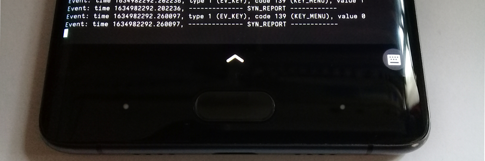
And just like that, we get working navigation buttons on Linux.
Unfortunately those buttons are not utilized much in userspace yet. The only things I found that react to pressing them are Firefox, which uses the back key to – you guessed it – go back, and GNOME Control Center, where pressing the back key causes some strange behavior, making it randomly jump to the power or network section possibly due to a bug. This, however, is a topic for another post.